Flexible Liner Underground Technologies

Ancillary Equipment
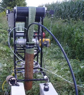
The Green Machine
The green machine is a name given to a system for removal of liners of several kinds using a wellhead roller and manual winch system. The green machine shown is positioned over the wellhead with the tether routed over the large roller, under a guide roller, to a manual winch capstan. The liner is inverted from the borehole until the tether attachment to the liner is reached. At that point, a kellum grip is attached to the liner and the removal is continued by routing the tether to a distant, well anchored snatch block and back to the winch on the green machine. This procedure is described in detail in a video teaching the installation and removal of blank liners. Contact Solinst Flute for access to the video. The green machine is frequently equipped with a load cell to monitor the tension being applied to the liner. However, if the force on the winch handle is not excessive, the tension on the liner system will not be excessive.

The Linear Capstan
The linear capstan is the Solinst Flute name for a motorized version of green machine. The machine shown in the photo is driven by a variable speed motor. The tether or liner is routed over the first two rollers, and then alternates under and over through the series of rollers. The friction on the several roller allows the motor to invert the liner from the borehole. The rollers are driven by a suitably routed chain such that the rollers all turn in the correct direction. This unique Solinst Flute machine can remove a liner with much less effort than the green machine with a modest tension on the liner beyond the machine. The tension is monitored with a pair of load cells. The motor speed, and therefore the tension on the liner, are adjusted and monitored with a separate controller. This machine is usually used by Solinst Flute personnel, but some units have been sold to customers with training in the use and maintenance.

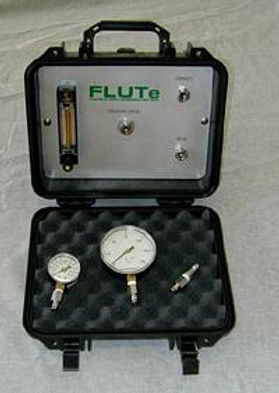
Bubbler Monitor
The water level in the liner during installation should be monitored with a water level measurement for deep water tables. For shallow water tables, the water level can often be maintained at the top of the casing. But for deep water tables, the water level should not be above ~20 ft higher than the water table in the formation. Monitoring the water level with the standard electric water level meter is frustrating due to the water being added to the liner as it descends. Therefore, an open tube, called a bubbler tube, is included in a sleeve of the standard liner to the water table. Connecting a controlled constant air flow source to the tube and monitoring the pressure variations as the water level rises in the liner allows easy control of a safe water level in the liner. That bubbler monitoring system can be purchased from Solinst Flute. The monitor must be connected to a gas bottle or compressor. The controller contains a flow meter and pressure gauge with a connection to the automatic data collection system if used with the profiling machine. The controller is usually used by Solinst Flute, but can be purchased.
The Profiling Machine
The transmissivity profile is performed with a unique Solinst Flute device called a profiling machine or Profiler. The Profiler controls the tension on the liner to be essentially constant and measures the depth and velocity of the liner propagation. The Profiler also measures the tension on the liner. This device, to date, has always been used only by trained Solinst Flute personnel. However, an “export model” has been designed and is being built for those distant locations where shipping and tariffs are prohibitively expensive and travel of Solinst Flute personnel to the site is also costly. This machine will be available to foreign users with the training for operation by Solinst Flute personnel. Since that training is extensive, the expense of a profiling machine is not practical for sites more proximate to Solinst Flute offices. Solinst Flute has many US and foreign patents on this method.
The Pressure Canisters
The pressure canister is use to evert liners into boreholes or tortuous passages with air as the driving fluid. This is most commonly the case for vadose systems or propagation of liners upward into drill holes from tunnels or into piping in buildings or landfills. The liner is loaded onto on interior reel and everted by air pressure supplied to the canister and thence into the liner. The canister size needed depends upon the size of the liner. These canisters are manufactured in various diameters of 1.5, 2, 3, and 4 ft. While not often sold, some sizes are available for purchase. The canister is especially useful for inverting a liner from inside-out to right-side-out. These canisters are used extensively in the fabrication of liners.

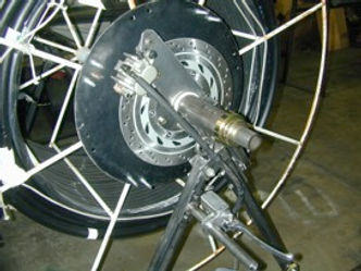
Shipping Reel Braking System
For very deep water tables and for large tubing bundles associated with many ports on a Water Flute system, the hanging load of the liner being installed into the borehole can exceed several hundred pounds. In order to control the descent of the liner and to support the large hanging load, a braking system has been designed, and used, which attaches to the shipping real on the reel stand. The braking system allows an easy and safe control of the liner descent with a disk brake and also monitors the tension on the liner by measurement of the torque on the reel. This device is not sold, but it is often rented for the installation of large liner systems where the control of the brake is required. This device is also necessary if there is a large downward gradient in the formation which is pulling the liner into the borehole with high tension.
The ACT (Air Coupled Transducer) System
Whereas the ACT system is usually sold as part of a Water Flute system, the ability to measure the fluid level continuously through a slender tube (e.g., 1/8” OD) has uses in other situations. The ACT system consists of a simple tube lowered below the water table, or other fluid level, with a sensitive transducer connected to the top of the tube. As the water level changes in the tube, the pressure measured in the tube also changes. From that pressure data and the temperature measured in the transducer, the history of the fluid level can be deduced with surprising accuracy. The test in a pumped domestic well with abrupt drops and recoveries of the fluid level showed the monitoring of a water table at a depth of 48 ft to be accurate within ¼” on the 1 second time scale. With different tubing geometries, the resolution will be different. The advantage of the ACT system employed in the Water Flute system is that the transducers are easily accessible at the surface for repair, replacement or reuse. This system can also be used where other deep installations of transducers are usually needed in confined circumstances. It also allows level measurements in tubing that is already in place for other purposes. Solinst Flute provides the software for converting the pressure and temperature measured to level changes. This method is not to be confused with the common bubbler system described above. ThIs system is available for the list price of the recording transducer and tubing. Flute has US and foreign patents on this method.
